Gents,
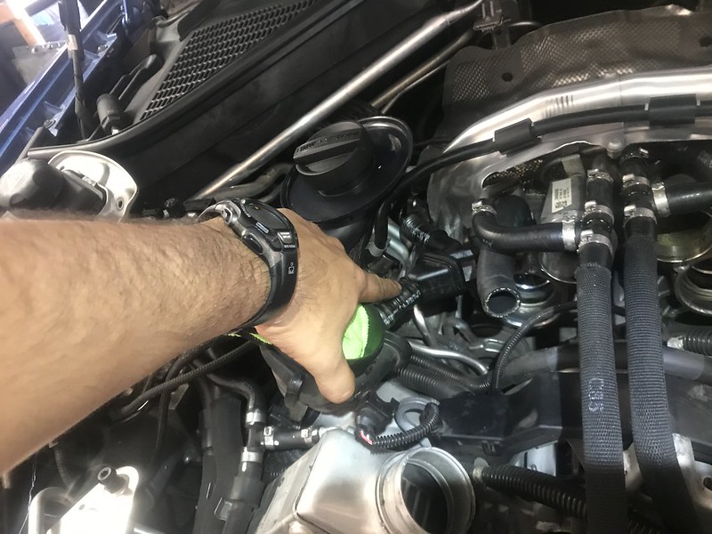
While cleaning up the engine bay I noticed that there was some oil leaking out of one of my Filtered Air Duct hoses and from one of my Charge Air Duct hoses. My warranty is up soon and I wanted to get the truck checked out beforehand without paying for these parts that werent covered. If you dont know, they usually try to find stuff that isnt covered and make you pay for that before they fix anything that is covered under warranty. I got some wisdom from M5James about replacing the Charged Air Duct Hoses and set to work. Along the way I found that the filtered air duct gasket on the other side was bad and I needed to replace that so I had to wait and order it. Also, when taking apart the diverter valves (wastegate bypass electronic valves) one completely fell apart and the spring disappeared into the engines V. Rather than order a whole new DV I bought the Go Fast Bits DV+. Ill post about that in another thread.
DIY: FILTERED AIR DUCT AND CHARGE AIR DUCT HOSES
NOTE: I RECOMMEND THAT ALL MAINTENANCE IS COMPLETED BY A CERTIFIED MECHANIC;This DIY is merely a record of what I did to complete this vehicle maintenance; I DO NOT RECOMMEND COMPLETING THIS YOURSELF.
NOTE: I took time and cleaned all of the parts before reinstalling including cleaning o-rings. I also used clean fresh engine oil to lubricate o-rings when installing or reinstalling parts to include the Filtered Air Duct hose connecting to the engine. I used my best judgement when torqueing the majority of the bolts except for the oxygen sensors since I knew the factory torque spec. I made sure to disconnect the battery since I was working next to a live wire underneath the Charge Air Duct. Also, the pictures may indicate the steps in the incorrect order, I adjusted the order to a better plan than what I did in reality; the typed steps are correct.
Parts Needed:
1 x Filtered Air Duct Cylinders 1-4 PN: 13717848151
1 x Filtered Air Duct Cylinders 5-8 PN: 13717848152
2 x 57mm (2-1/4) Inner Diameter (ID) Silicone Intercooler Coupler Hose
2 x 60mm (2-3/8) Inner Diameter (ID) Silicone Intercooler Coupler Hose
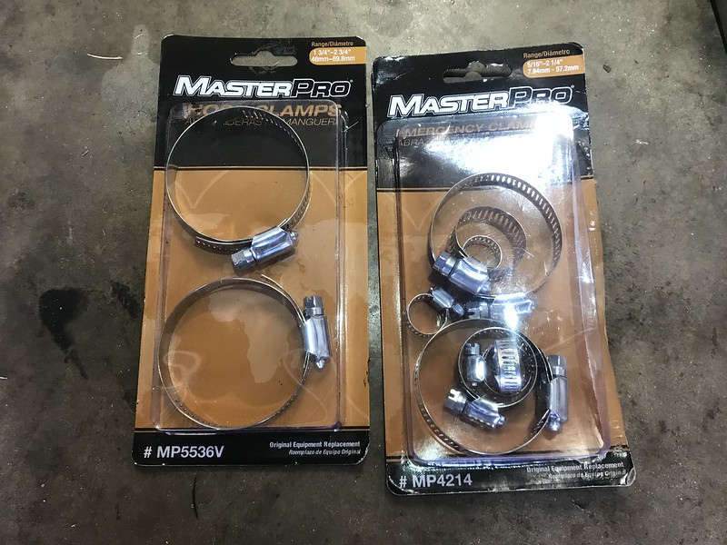
8 x 2-3/4 Hose Clamps
2 x 1-1/2 Hose Clamps
Tools Needed:
1/4 Drive Ratchet
1/4 Drive Extensions
3/8 Drive Ratchet
3/8 Drive Extensions
3/8 Drive Torque Wrench
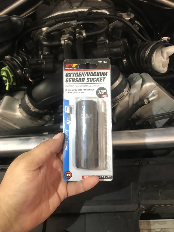
7/8 Oxygen Sensor Socket (Cutaway Style; 3/8 Drive)
13mm Socket
10mm Socket
10mm Deep Socket
8mm Socket
6mm Socket
T25 Torx Bit
T30 Torx Bit
E8 External Torx Bit
Philips Head Screwdriver
Flat Head Screw Driver
Small Flat Head Screw Driver
Needle nose pliers
Box Cutter
STEP 1: Disconnect the Battery
a) Open rear hatch
b) Lift Cargo Floor
c) Loosen and remove 4 x 8mm screws and 1 x Philips head screw from battery cover
d) Remove Plastic battery cover
e) Use 10mm socket to loosen and remove negative terminal wiring
f) Move wiring to the side; place non-conductive material between wiring vehicle
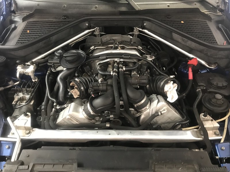
STEP 2: Remove Engine Cover and Intake Silencer (Airbox)
a) Pop the hood using latch near drivers foot rest
b) Lift hood using lever centered under kidney grills
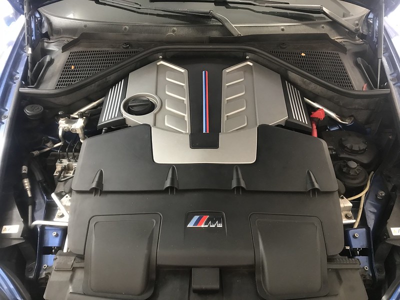
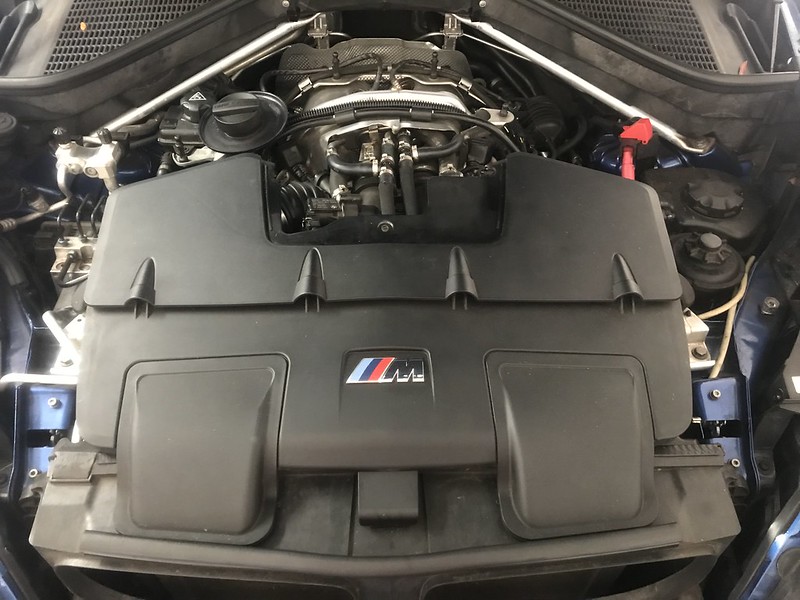
c) Lift off plastic engine cover, pulling up on 4 x pressure/grommet fittings under the cover
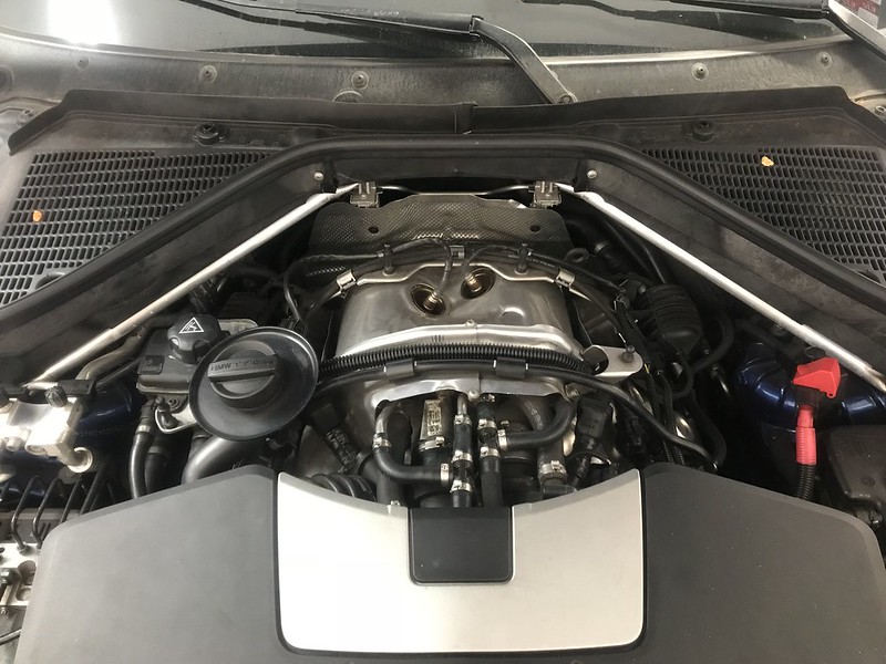
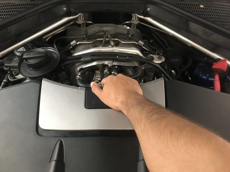
d) Remove air silencer plastic insert, grabbing and pulling toward the rear of the vehicle
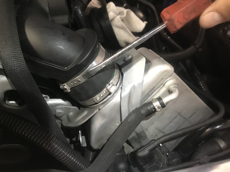
e) Loosen hose clamps connecting air silencer to air duct using 6mm socket, 1 x clamp per bank
f) Lift to disconnect 3 x pressure/grommet fittings under the air silencer, pull air silencer assembly out of the passenger air duct first, then driver side air duct to remove
g) place clean cloth inside air ducts to prevent debris from entering the turbochargers
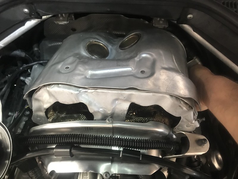
STEP 3: Remove Turbocharger Heat Shielding
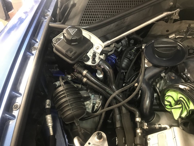
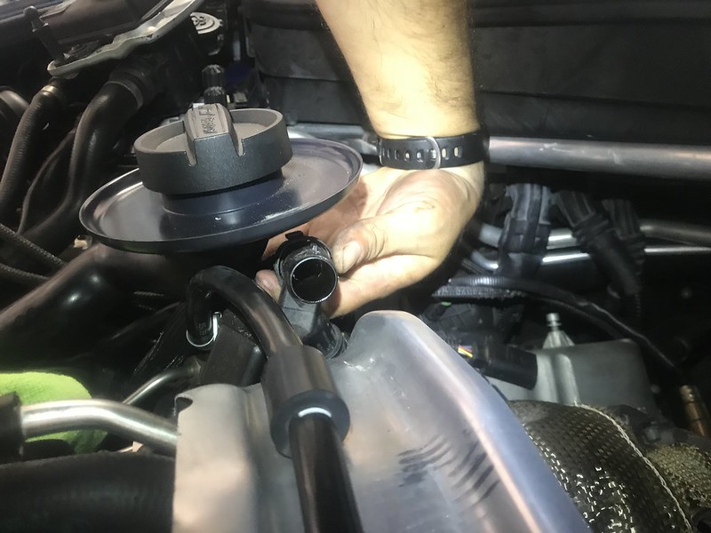
a) Loosen and remove 2 x 10mm bolts securing Intercooler Expansion Tank
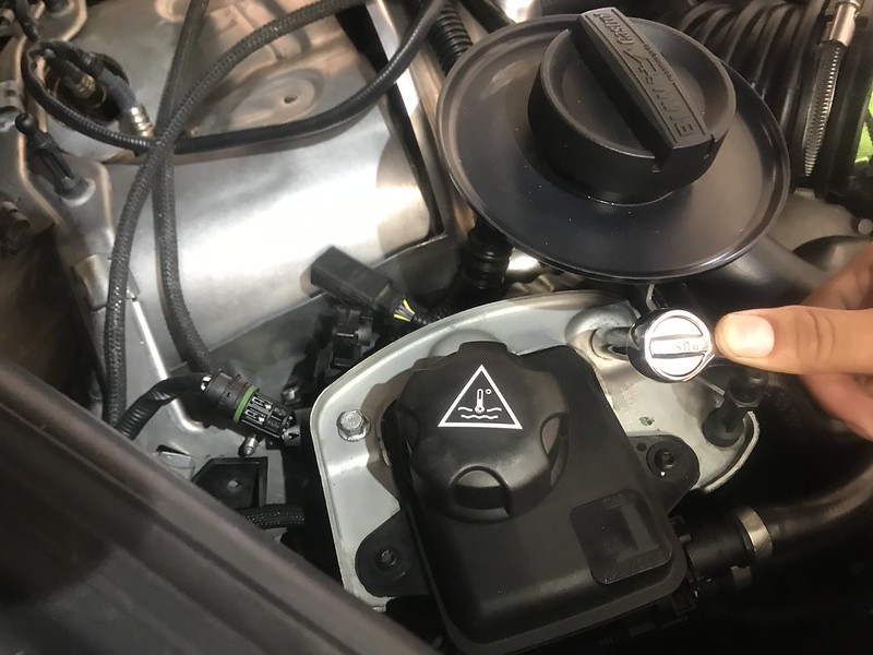
b) Lift expansion tank up and out of the way, resting it on HVAC hoses. Watch for leaks from cap (normal)
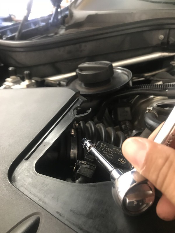
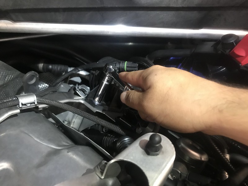
c) Disconnect oxygen sensor wires and remove from heat shield bracket, two each bank

d) Loosen and remove 10mm washer nuts from plastic vacuum tanks, one per bank
e) Unclip vacuum hoses from heat shield bracket and move vacuum control hose assembly off to the passenger side, resting on ABS module.
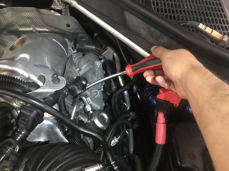
f) Loosen and leave T30 Torx bolts securing heat shield bracket, 2 each bank
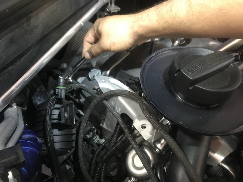
g) Lift to remove heat shield bracket
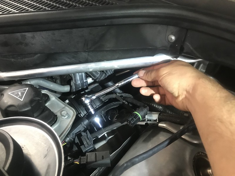
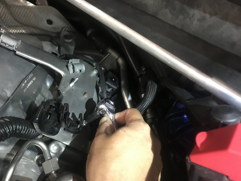
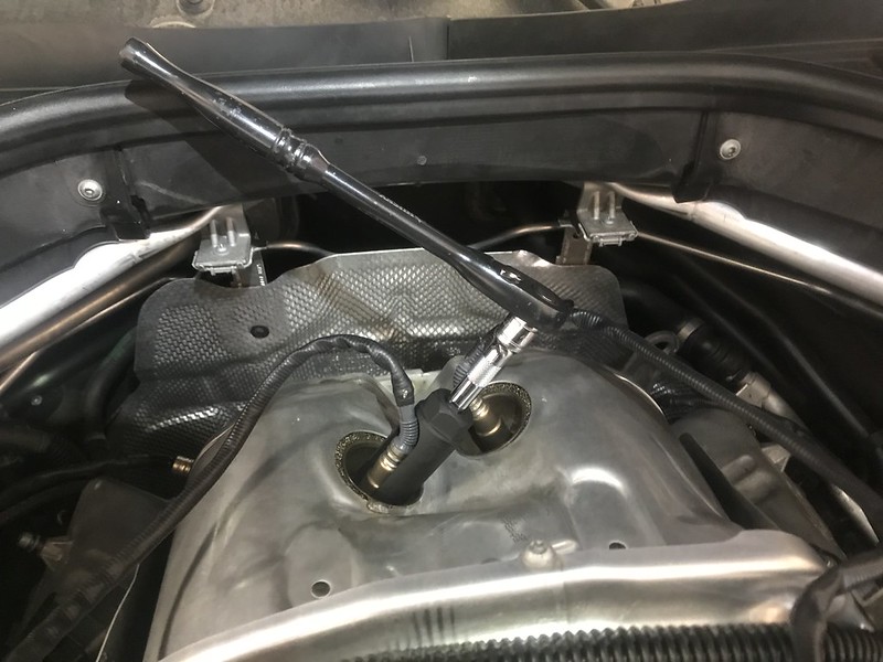
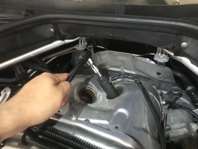
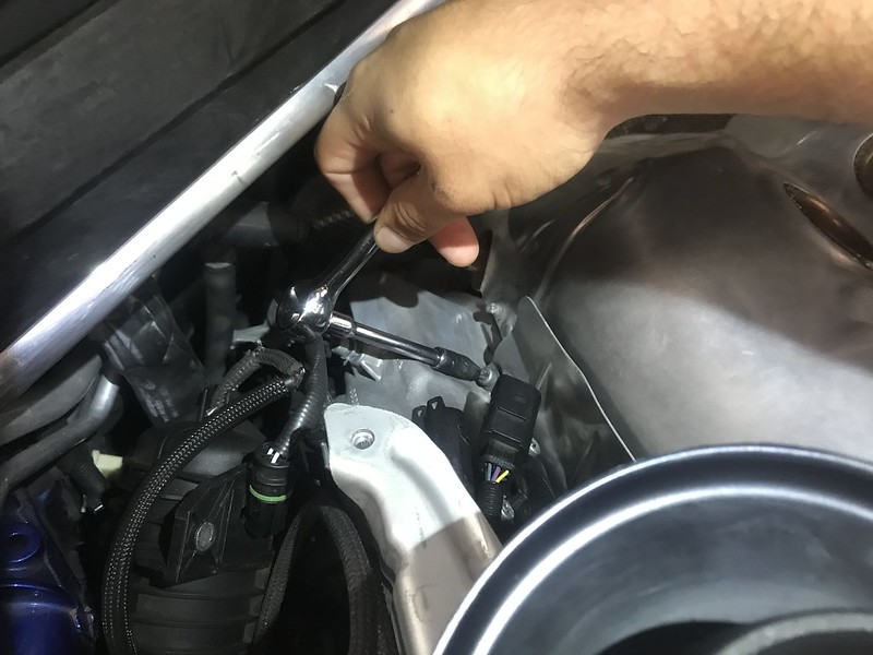
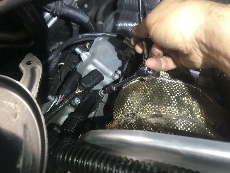
h) Loosen and remove oxygen sensors using 7/8 oxygen sensor socket
i) Loosen and remove E8 External Torx bolts securing the left and right wing heat shields, 2 each side
j) Lift out to remove the left and right heat shielding
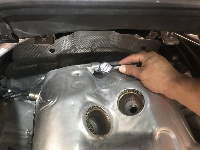
k) Loosen and leave E8 External Torx bolts securing turbocharger heat shield to engine, 3 each bank
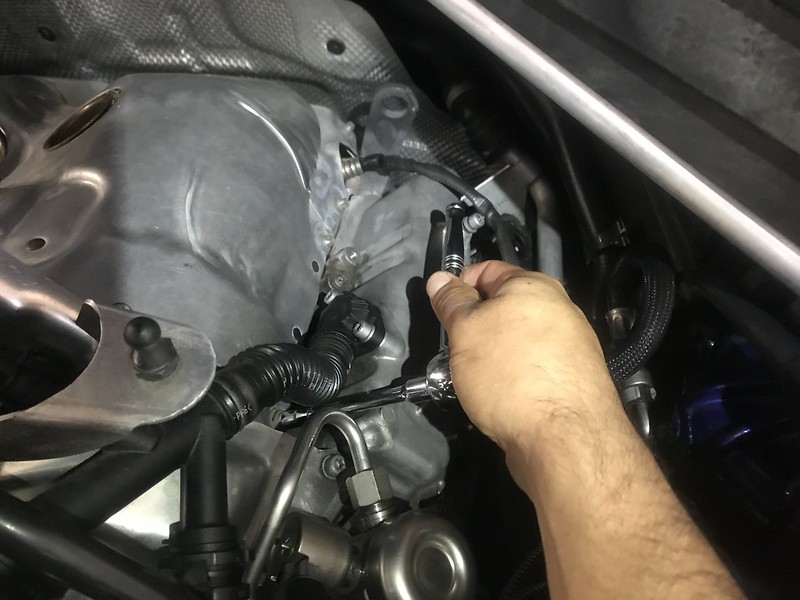
l) Loosen and remove E8 External Torx bolts securing turbocharger heat shield to downpipe heat shielding, 3 total
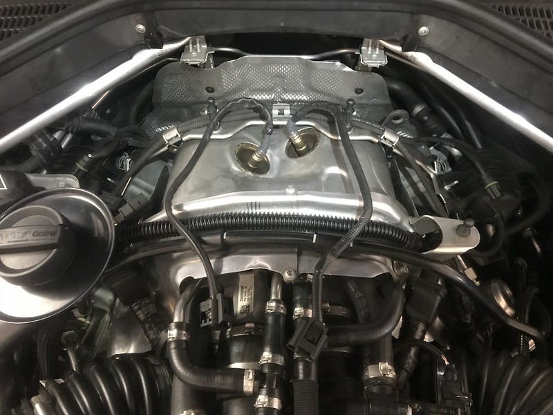
m) Lift up and remove turbocharger heat shield
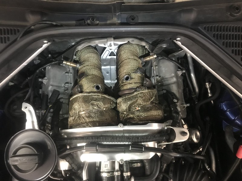
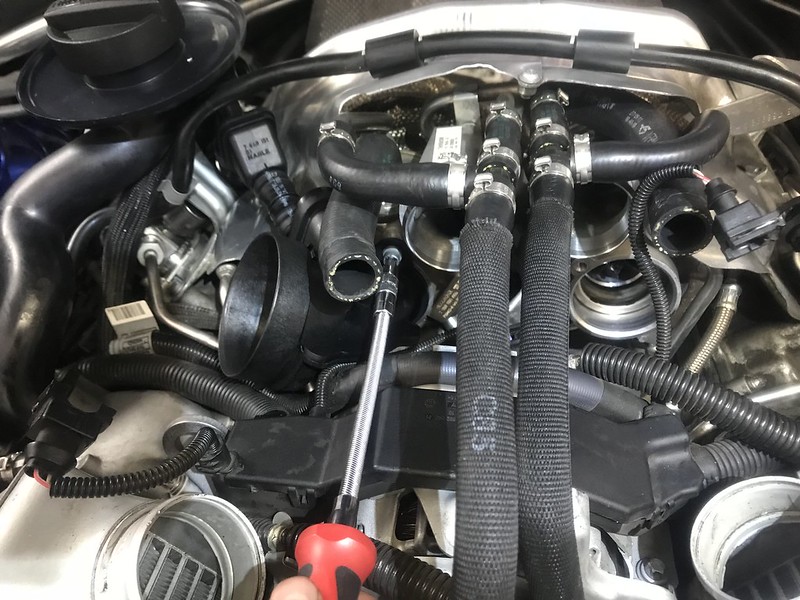
STEP 4: Remove Charged Air Duct (Charge Pipe)
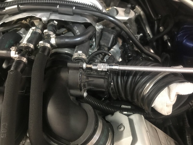
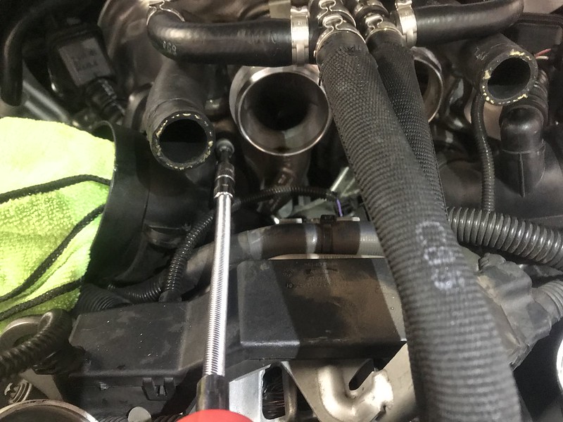
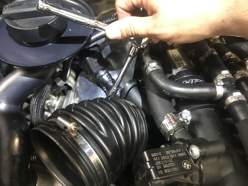
a) Loosen engine-side hose clamps on intake air duct rubber boots using 6mm socket, one hose clamp each bank
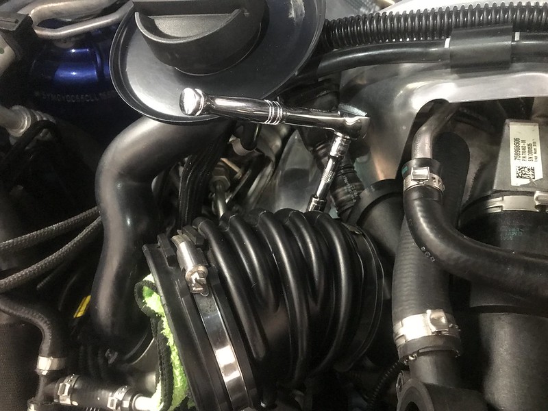
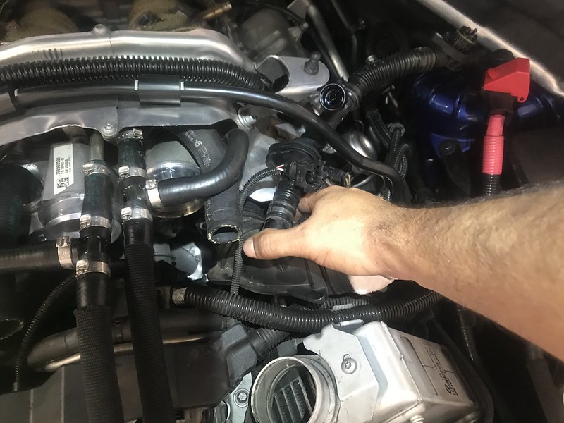
b) Remove left and right intake air duct rubber boots
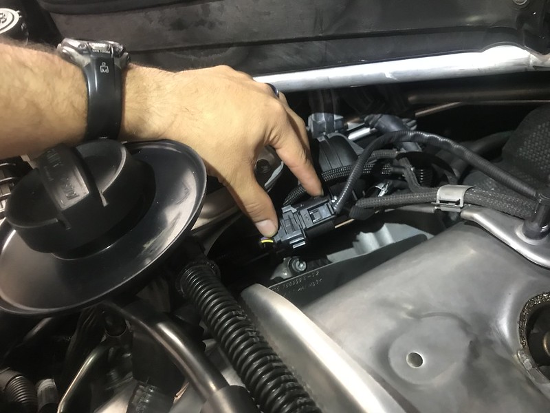
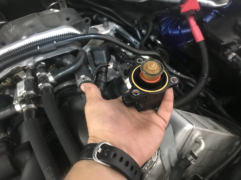
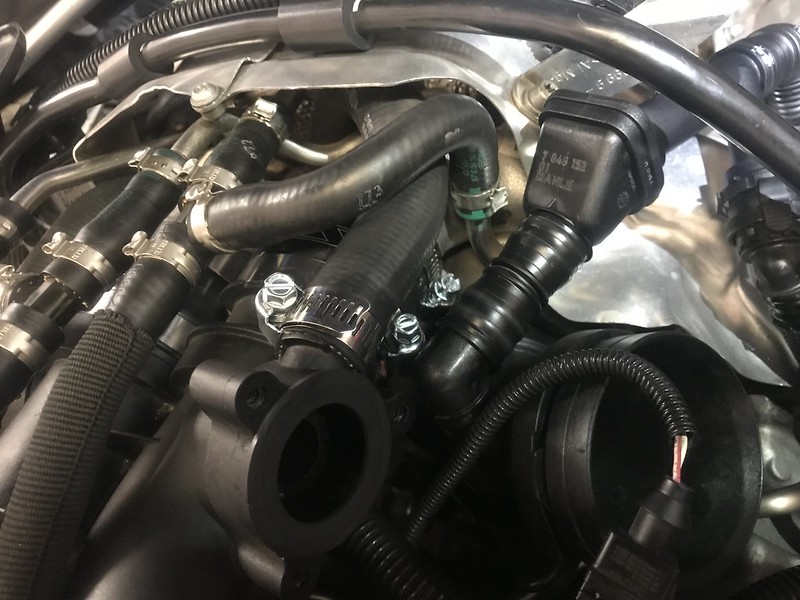
c)Disconnect the wire clips on the Wastegate Bypass Electronic Valves
d) Loosen and remove T25 Torx Bolts securing the wastegate Bypass electric valves and remove the valves, 3 bolts each side (TAKE SPECIAL CARE WHEN REMOVING VALVE AS THE INTERAL PARTS MAY FALL APART AND CAUSE YOU TO LOOSE A PART)
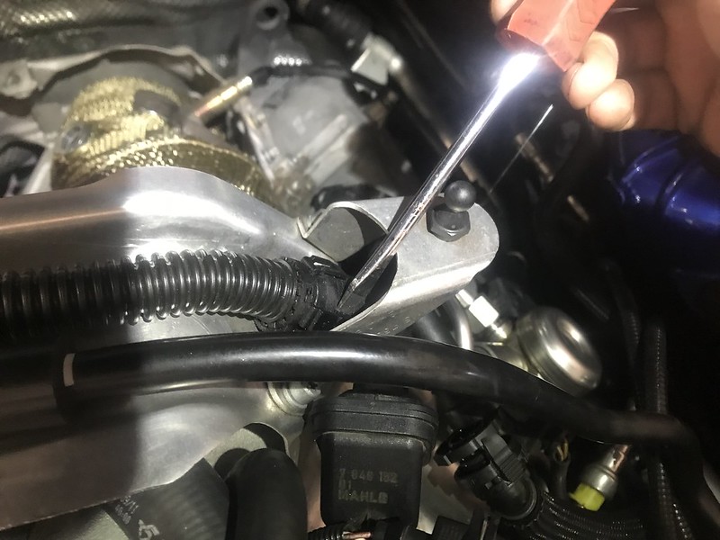
e) Pry up and remove wastegate bypass hose clamps, one each side of charged air duct using flat head screwdriver and pliers
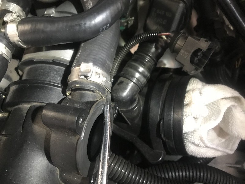
f) Disconnect wastegate bypass hose from charged air duct
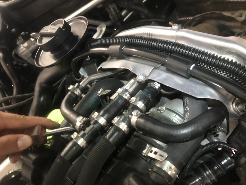
g) Pry up and remove charged air duct to intercooler hose clamps using flat head screw driver and pliers, 2 each side
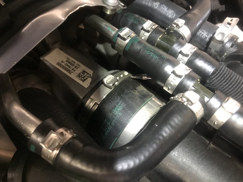
h) Pry up and remove turbocharger to charged air duct hose clamps, 2 each side (THIS IS DIFFICULT SINCE YOU MUST MANUEVER AROUND TURBOCHARGER COOLANT HOSES)
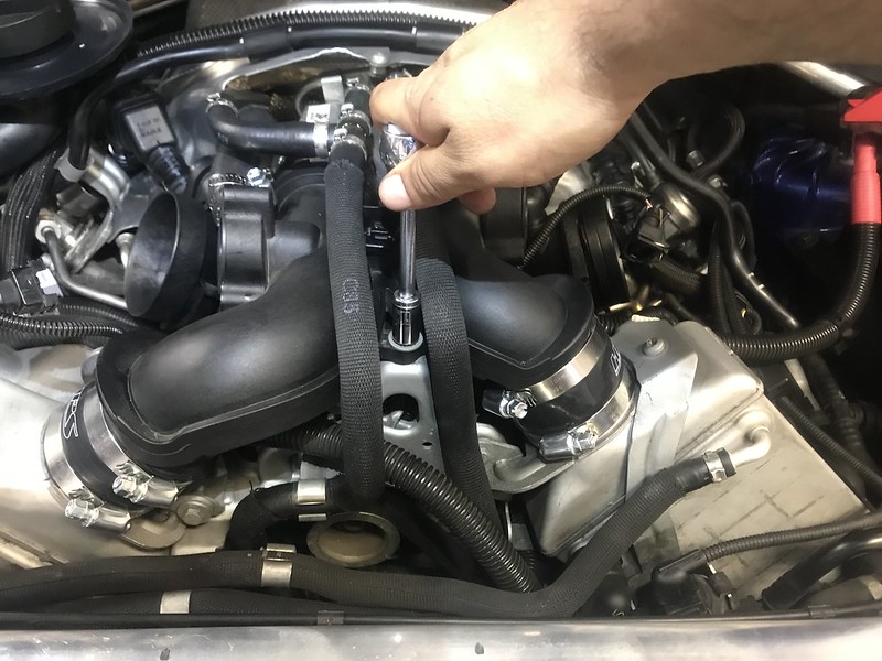
i) Loosen and remove 10mm bolt securing the charged air duct to the engine
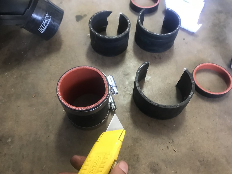
j) Carefully cut a slice into charged air duct to intercooler hoses using box cutter, one hose each side (BE CAREFUL, CUT ON INTERCOOLER SIDE OF HOSE AND PRY UP HOSE SINCE THEY ARE STUCK ON TIGHT)
k) Carefully cut a slice into turbocharger to charged air duct hose using box cutter, one hose each side (BE CAREFUL, CUT ON TURBOCHARGER SIDE OF HOSE AND PRY UP HOSE SINCE THEY ARE STUCK ON TIGHT; WATCH OUT FOR THE TURBOCHARGER COOLANT HOSES)
l) Unclip the passenger side turbo charger coolant hose from the front of the engine (DO NOT DISCONNECT THE HOSE IN ANY WAY; THERE IS A METAL CLIP THAT JUST SECURES THE HOSE TO THE FRONT OF THE ENGINE)
m) Remove charged air duct (BE CAREFUL, TAKE YOUR TIME AND WATCH OUT FOR THE TURBOCHARGER COOLANT HOSES.
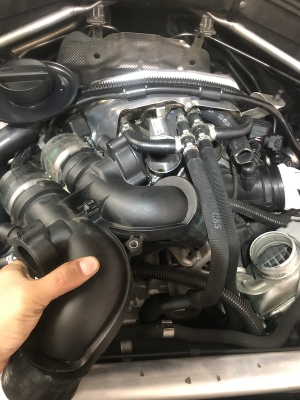
STEP 5: Remove Filtered Air Ducts
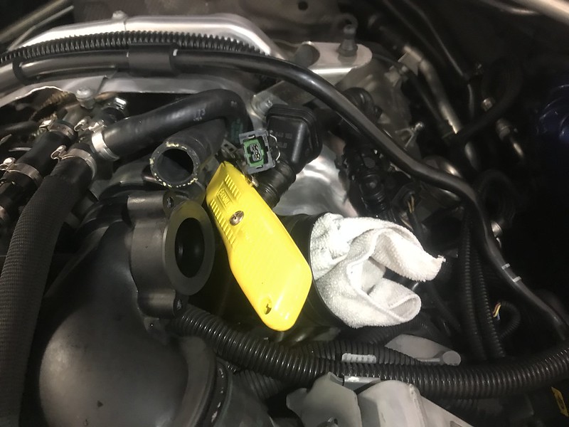
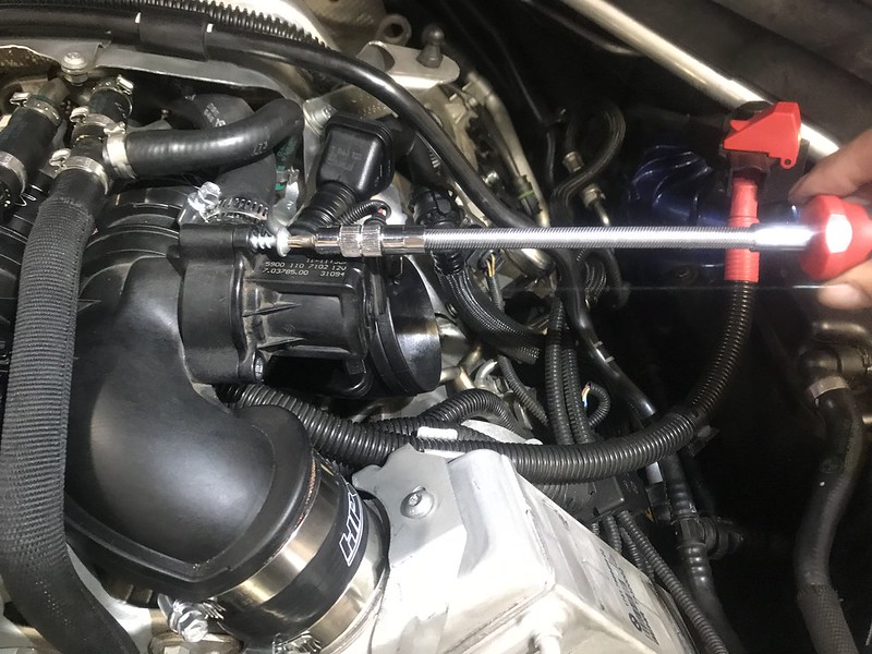
a) Loosen and remove T30 Torx bolts securing the Filtered Air Duct hoses to the engine, two each bank

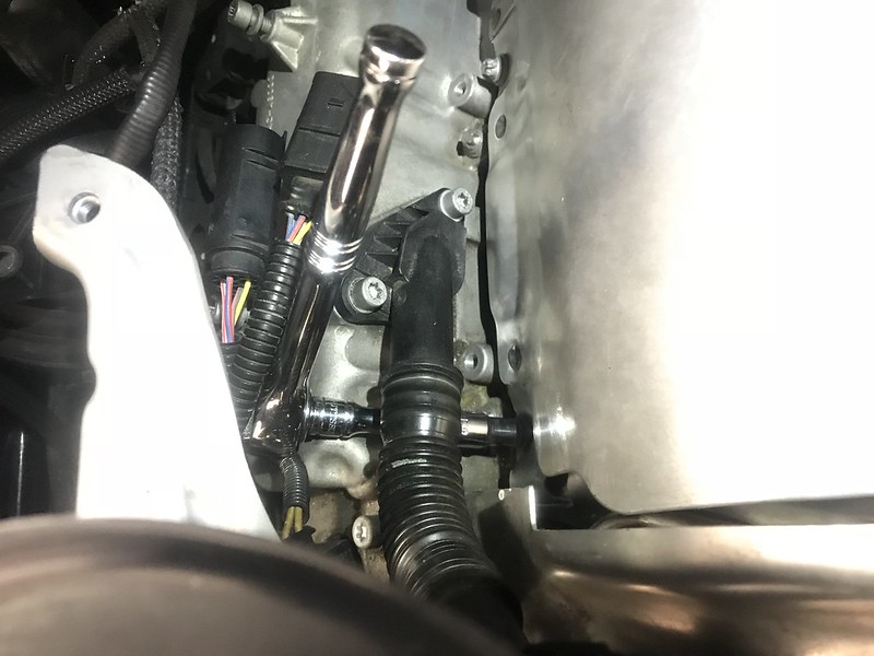
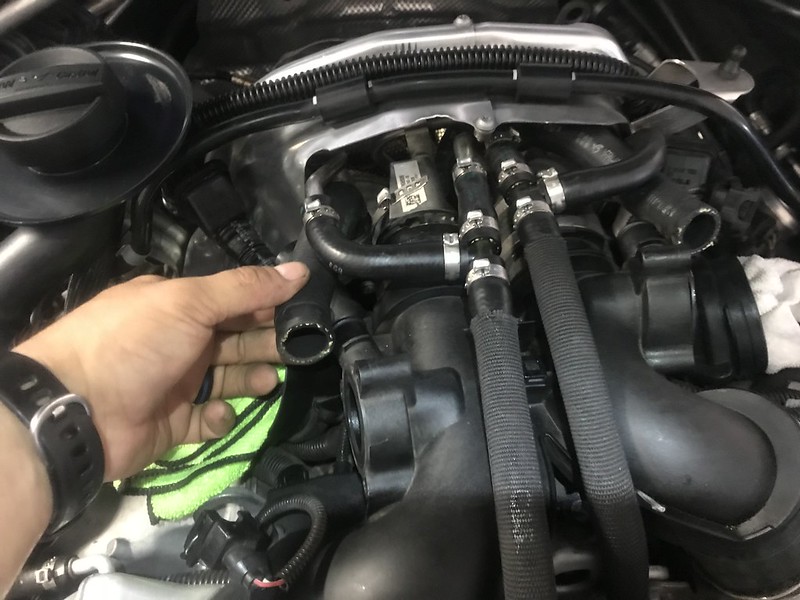
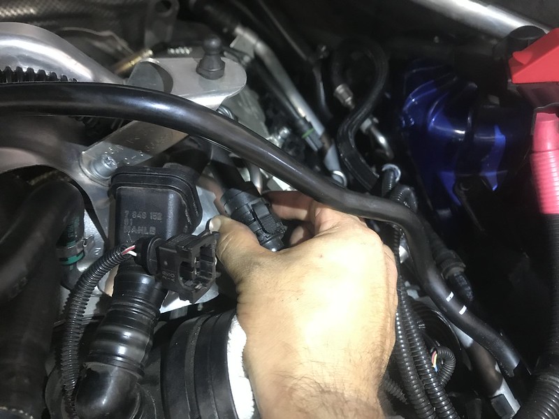
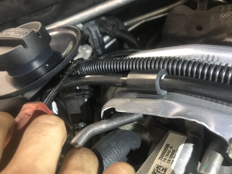
b) Unclip the Crankcase Vent Pipes from the Filtered Air Duct hoses using thumb and index finger pressure to separate, one each side
c) Unclip the Crankcase Vent Pipe Connecting Line from the Filtered Air Duct hoses using flat head screwdriver to pull apart, one line connecting the two Air Duct hoses
d) Loosen and remove the T30 Torx bolt securing the Filtered Air Ducts to the Turbochargers, one per Air Duct

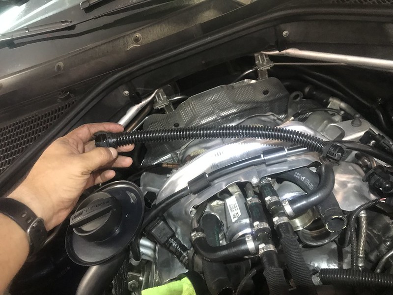
e) Remove Filtered Air Ducts
STEP 6: Install New Filtered Air Ducts
a) Loosen hose clamp securing the new Cyl 5-8 Filtered Air Duct Rubber Boot (Drivers Side) using 6mm socket and remove the rubber boot
b) Install new Filtered Air Ducts aligning the hoses to the engine and the duct to the turbochargers
c) Secure the Filtered Air Ducts to the Turbochargers using T30 Torx bolts
d) Reconnect the Crankcase Vent Pipe Connecting Line to the Filtered Air Duct hoses
e) Reconnect the Crankcase Vent Pipes to the Filtered Air Duct hoses
f) Secure the Filtered Air Duct hoses to the engine using T30 Torx bolts, two bolts each side
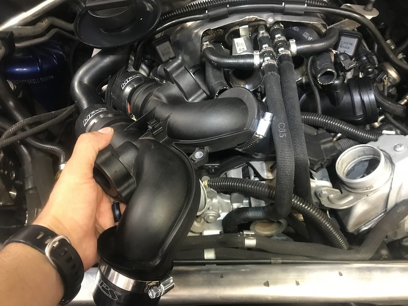
STEP 7: Install Charged Air Duct
a) Carefully cut a slice through the Charged Air Duct hoses, 4 total hoses (BE CAREFUL, THE CHARGED AIR DUCT IS PLASTIC, ONLY CUT DEEP ENOUGH TO CUT THROUGH THE RUBBER HOSE FOR REMOVAL)
b) Peel off the old hoses and mark which hose went to which corner of the Charged Air Duct
c) Use The old hoses and your new hose clamps to mark appropriate cutting locations on the new hoses
d) Use the new hose clamps as guides for cutting the new hoses to appropriate length (ENSURE YOU ARE USING THE CORRECT NEW HOSE AND THE CORRESPONDING OLD HOSE, THE HOSES ARE SLIGHTLY DIFFERENT LENGTHS DEPENDING ON LOCATION)
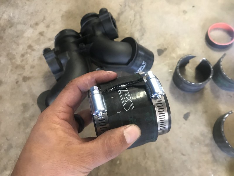
e) Prepare new hose clamps to fit over new hoses with small amount of movement ability
f) Place Turbocharger to Charged Air Duct hoses on the Charged air pipe with both sets of hose clamps on, two hose clamps per hose
g) Place Charged Air Duct to Intercooler hoses on the intercoolers with both sets of clamps on, two hose clamps per hose (NOTE: THE PICTURE IS INCORRECT, I LEARNED WHILE INSTALLING THAT YOU MUST PLACE THE CHARGE PIPE TO INTERCOOLER HOSE ON THE INTERCOOLER DURING INSTALLATION)
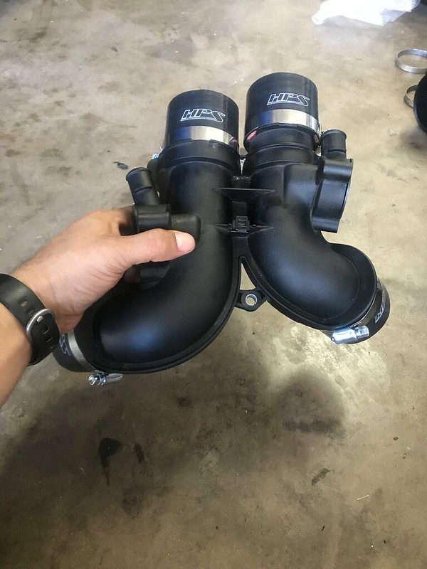
h) Install the Charged Air Duct, lining up the turbocharger hoses first and then the intercooler hoses (BE CAREFUL WORKING AROUND THE TURBO CHARGER COOLANT HOSES)
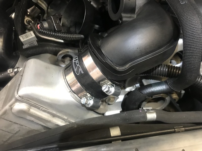
i) Tighten the hose clamps on the Turbochargers, Charged Air Ducts, and Intercoolers, 8 total hose clamps
j) Place new small hose clamps on the Wastegate bypass hoses, one each side
k) Reconnect the Wastegate bypass hoses to the Charged Air Duct, one each side
l) Tighten down the hose clamps on the Wastegate Bypass hoses, one each side
m) Reinstall the Wastegate Bypass Electronic Valves using T30 Torx bolts, 3 each valve (BE CAREFUL WHEN HANDLING WASTEGATE BYPASS ELECTRONIC VALVES AS THEY CAN FALL APART EASILY)
n) Reconnect Wastegate Bypass Electronic Valve wiring
o) Insert and Tighten 10mm bolt securing the Charged Air Duct to the Engine
p) Reinstall Filtered Air Duct Rubber Boots onto the Filtered Air Ducts and secure using OE hose clamps and 6mm socket
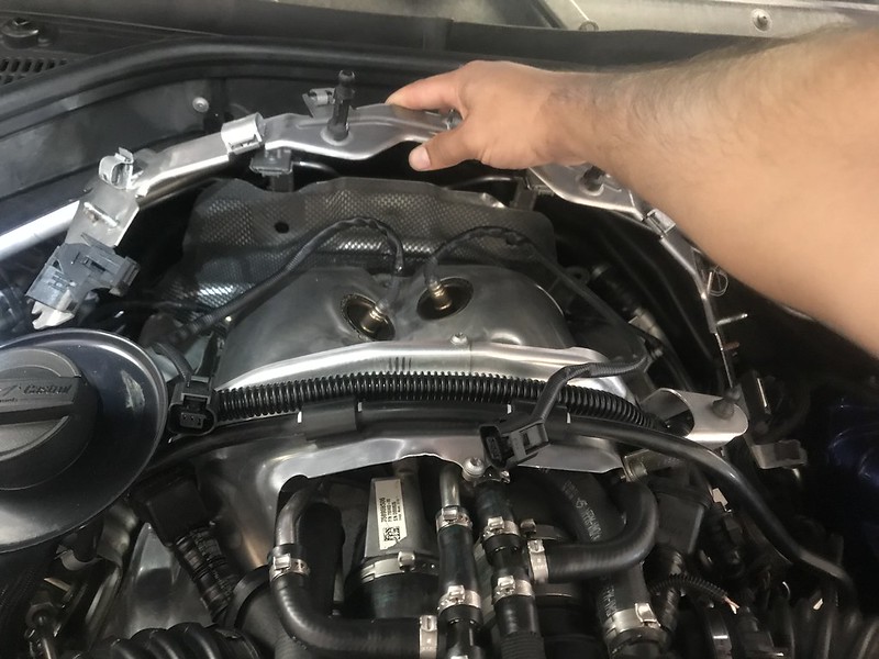
STEP 8: Reinstall Turbocharger Heat Shielding
a) Loosen Turbocharger Heat Shielding E8 External Torx bolts until they are nearly all the way out but still secure, 3 bolts each bank
b) Place Turbocharger Heat Shielding in place ensuring that the E8 External Torx bolt washers are on the exterior of the Heat Shielding
c) Install and tighten E8 External Torx bolts securing the Turbocharger Heat Shielding to the Downpipe Heat Shielding, 3 total
d) Tighten the E8 External Torx Bolts securing the Turbocharger Heat Shielding to the engine, 3 bolts each side
e) Insert Left and Right Wing Heat Shielding and secure using E8 External Torx bolts, two each side
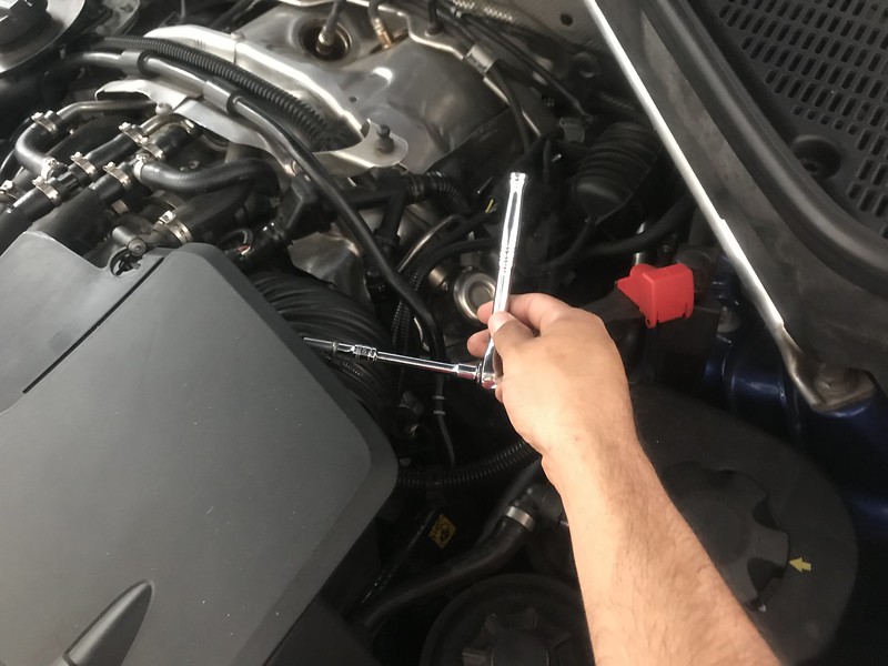
f) Reinstall Oxygen Sensors using 7/8 Oxygen Sensor Socket and Torque wrench set to 29ft lbs
g) Reinstall Heat Shielding Bracket, ensuring that the T30 Torx bolt washers are on the exterior of the bracket and tighten bolts, 2 bolts each side
h) Reconnect Oxygen Sensor wires to the Heat Shielding Bracket and plug them back in
i) Reinstall the Vacuum Control Hose Assembly, routing the hoses on the Heat Shielding Bracket, and secure using 10mm nuts and socket, 1 nut per side
j) Reinstall Turbocharger Coolant Expansion Tank, secure using 10mm bolts and socket, 2 total
STEP 9: Reinstall Intake Silencer and Engine Cover
a) Slide protruding portions of Intake Silencer into Filtered Air Duct Rubber Boots, Drivers Side First then Passenger side
b) Tighten hose clamp connecting Filtered Air Duct Rubber Boots to the Intake Silencer using 6mm socket, one each side
c) Slide Air Silencer Plastic Insert into place
d) Place engine cover in place and press down, ensuring that all four pressure fittings secure
e) Close Hood
STEP 10: Reconnect Battery and Clear Codes
a) Reconnect the negative terminal wiring to the negative terminal of the battery
b) Tighten wiring down using 10mm socket
c) Replace Plastic Battery Cover and secure using 4 8mm bolts and 1 philips head bolt
d) Close storage compartment lid
e) Close Trunk
f) Turn Truck on and look for CEL or other Faults
g) If you get a Steering Angle Sensor Fault and several other DSC Faults and simply turn the steering wheel full lock left then full lock right and back to the center. The Faults should clear. If you have any other faults or CEL then use Carly/Dashcommand or run to autozone to get it checked out and cleared. After clearing codes turn the car off and let it sit for 10 minutes with the key away from the car. Restart the vehicle and look to see if the codes stayed cleared.