DASHCAM HARDWIRE DIY
[UPDATED: 18FEB2023 - Rewritten for Clarity and ease of use. NOTE this DIY does not tap into existing oem wires, the DIY uses fuse adapters and taps power from front fuse box under passenger side dash.]
IMPORTANT:
-This Thinkware F800 Dashcam is hardwired to the front fuse box using the Thinkware hardwire kit.
-Park Mode is functional only when dashcam installed with the hardwire kit (switch and constant power) and mode activated via Thinkware App.
-CONSTANT power from Fuse F10 (5A) used for Parking Brake and START/STOP per 2013 X5M Fuse Diagram. Fuse F10 located under passenger side dash fusebox. Do your own research to confirm.
-SWITCH power from Fuse F111 (20A) Luggage Compartment Fusebox Front Cigarette Lighter, Charging Socket Center Console Rear.
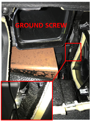
-GROUND is made on one of the screws behind the passenger side vent, to the right of glovebox. OR ground distribution block near Luggage Compartment Fusebox
OVERVIEW
OBJECTIVE: Hardwire DASHCAM to Passenger Side Fusebox
-Mount Dashcam on left side of interior rear view mirror
-Remove Passenger Side Lower Trim Panel, duct, and cable clamp
-Loosen passenger A-pillar screw and top rivet
-Pull door gasket away from work area
-Remove passenger side vent and trim
-Remove passenger side dash lateral trim piece
-Route hardwire cord across headliner to passenger A-Pillar, then down channel behind door gasket to right side of glovebox and into passenger side fusebox (Junction A4010)
-Crimp hardwire kit wires to Fuse Adapters and install Fuse Adapters into identified ACC and CONSTANT POWER fuse locations in fusebox A4010
-Fasten hardwire kit ground wire to vehicle ground screw
-Installation is reverse of removal
EQUIPMENT & TOOLS:
Dashcam: Thinkware F800 PRO, Front Camera only, 32GB
Thinkware Hardwire Kit Cable (TWA-SH)
Plastic Pry Tools
Philips Head Screwdriver
T20 Driver
T20 Long Neck, Socket
Long Flat Head Screwdriver
Friction Tape
Electrical Tape
10mm Socket (Negative Battery Cable)
8mm Socket (Battery Cover)
Wire Cutter (Small Gauge, 22-26ga)
Wire Cutter (Crimping)
Fuse Puller (out of A42 Junction Box, Trunk Fusebox)
ATC/ATO Fuse Adapters, 16ga, (
https://www.amazon.com/dp/B0722CF9FT/ref=cfb_at_prodpg)
ATC/ATO FUSES, 5A, 3A (one each, AutoZone)
 USING FUSE ADAPTERS
-See image below for schematic of Fuse Adapter. Place the OEM fuse in the bottom fuse location of the fuse adapter. Place the dashcam fuse in the upper fuse location of the fuse adapter. Note that the dashcam fuse must be of lower amperage than the OEM fuse. Also note the fuse adapter blade labeled 12V (HOT), must plug into the HOT leg of the oem fuse location in the fusebox.
-I used 16ga Fuse Adapters, but if you can get lower gauge fuse adapters do so. The hardwire kit uses 22-26ga wire, so crimping these together is not ideal, the adapter is much heavier and will strain the connection. As such, I stripped enough wire on each hardwire kit wire to double over and then crimp to the fuse adapter. Also, I wrapped the crimp with friction tape to create some stress relief for the 26ga wire. I used a small bit of electrical tape to secure the end of the friction tape.
-The hardwire kit wire labeled “ACC” (red wire) is connected to the SWITCHED POWER fuse F6 which uses an OEM fuse of 10A. I chose a 5A fuse for the dashcam wiring.
-The hardwire kit wire labeled “BATTERY” (yellow wire) is connected to the CONSTANT POWER fuse F10 which uses an OEM fuse of 5A. I chose a 3A fuse for the dashcam wiring.
-I’m not certain if the camera fuses I chose are too high or too low. If someone can fill in the blank here, we’d all appreciate it. I believe the hardwire kit came with its own inline fuses, so this may be a moot point.
 WHICH FUSES TO USE: Constant/HOT, Switch/ACC, Ground
-DISCLAIMER:
WHICH FUSES TO USE: Constant/HOT, Switch/ACC, Ground
-DISCLAIMER: My vehicle is a May 2013 build, E70 X5M, and I used the fuse diagrams within the vehicle, and you should do the same. I noticed that searching in various internet locations for information, not everything aligned to my vehicle's fuse diagrams. Also, I’m posting these instructions so that you can just use the fuses I selected with all work being performed with the BATTERY DISCONNECTED. DO NOT randomly pull fuses with vehicle ON, ACC, or SLEEP modes without performing your own research. Avoid any wiring or fuses connected to the Footwell Module (IE: F23, F33, F34, F96) as we all know that module is very sensitive.
IMPORTANT REFERENCE, See Page 15, Post#313 for details on HOT/ACC/GND selection: https://www.bimmerpost.com/forums/sh...php?p=29884558
There are several variations of SWITCH fuses that can be used and depending on your selection the operation of the dashcam varies as follows:
OPERATION Option-1: From a completely powered down vehicle (after 30minutes of inactivity, IE: SLEEP Mode) and using
Fuses F10/HOT and F111/SWITCH,
the dashcam turns ON when the vehicle engine is switched ON. With either of these connections removed, the dashcam does not operate with vehicle in Sleep, ACC or Engine On.
Using these fuse selections, the dashcam will turn OFF when the engine is turned OFF.
OPERATION Option-2: From a completely powered down vehicle (after 30minutes of inactivity, IE: SLEEP Mode) and using
Fuses F10/HOT and F18/SWITCH,
the dashcam turns ON when the vehicle alarm is deactivated or the door handles are pulled opened. With F10/HOT connection removed, the dashcam does not operate with vehicle in Sleep, ACC or Engine On.
Using these fuse selections, each time you open the vehicle door the dashcam will turn on and begin recording until it goes into SLEEP mode.
-CONSTANT POWER - I chose to use fuse F10, 5A which is HOT (12V) when the vehicle is completely powered down. Per the fuse diagram, fuse F10 is used for the Parking Brake and START/STOP systems.
-SWITCH POWER – I chose to route cable from a fuse adapter on the luggage compartment fusebox fuse F111, 20A which was tested to be true ACC/Switch power.
-GROUND – I chose to route cable from a ground distribution block near the luggage compartment fusebox. Optionally, you can use a screw found behind the passenger air vent. If you’re device doesn’t work, then try a new ground location. There are effectively three screws and one large black nut visible in that area, but only one of those worked. One screw mounts an electrical module to a small shiny bracket. I mounted the ring connector from the hardwire kit underneath the washer of this screw and it was acceptable (confirmed w/multimeter and constant power search above). Most times you want to get the ground ring between the screw head and washer, but I couldn’t immediately separate the two enough to fit the ground ring between the two. I also used this space to house the excess cable from the hardwire kit.
-NOTE: Once I unlocked the vehicle, the instrument cluster and associated electronics shut down under 5 minutes. At 8 minutes, the interior lights shut off. Note that opening/closing doors, pressing seat buttons, or compressing the suspension may activate/awaken systems.

 DISCONNECT NEGATIVE BATTERY CABLE
-Use 8mm Socket for Storage Trim
-Use 10mm Socket for Negative Battery Cable removal
-Installation is reverse of removal.
REMOVE INSTRUMENT PANEL TRIM, BOTTOM RIGHT
-Two screws are T-20 and one is a PHILLIPS
-Remove light connector and secondary connector that is mechanically attached to smaller removable flap in Panel Trim. Installation is reverse of removal.
REMOVE AIR DUCT, BOTTOM RIGHT
-Remove two T-20 screws and firmly pull assembly straight down and out. Installation is reverse of removal.
LOOSEN HARNESS CLAMP (Optional)
-This step is optional, see RELEASE PASSENGER SIDE FUSEBOX HINGE below for details. See image below. There is a large bundle leaving the fusebox and heading to the center of the vehicle. To the left of the fusebox there is a clamp with integrated duct held on with two T-20 screws that can be removed to loosen the bundle and provide additional slack when working with the released fusebox. Top screw removal is better served with a long neck T20 socket and extension. Bottom screw has potential to fall out behind the insulation, adding more time to your job. Installation is reverse of removal.
 RELEASE PASSENGER SIDE FUSEBOX (A4010) HINGE (Optional)
-The fusebox is hinged at the rear and lowers down after unscrewing a single captured phillips head green screw located center front of the fusebox. Note, I have medium size hands and after the fact realized that I didn’t need to release the fusebox hinge or remove the harness clamp, but extra room always helps. The fusebox is hinged against two tab shaped flat plates with through holes protruding from the chassis. The image below shows one side. The fusebox has two corresponding flat tabs with short fat pin features protruding that lock into the chassis tab through holes. By prying the tabs apart, the fat pins slide out of the sockets releasing the fusebox. This provides extra room for you to work. The fusebox hinges are easier to see when the fusebox is up, but easier to remove when the fusebox is down. Place a long flat head screwdriver between the fusebox grey plastic plate and the chassis metal black plate and rotate screw driver to pry apart while simultaneously gingerly rotating fusebox to disengage. Repeat for the other side and it releases. Note that sometimes I would release one side and just as I got the other side released, the first side would snap back in…patience. This goes back together much easier than removal, just press fusebox into hinge, rotate to ensure it’s secure, and double check by eying the hinges.
 LOOSEN A-PILLAR TRIM
-No need to remove the A-pillar, only loosen. Remove the AIRBAG tab using plastic pry tools, and then remove the T-20 screw. Pull from the top until you hear the top plastic rivet pop and release. This gives you some flex to route the hardwire cable down to the lower passenger fusebox. Installation is reverse of removal.
REMOVE PASSENGER FRESH AIR GRILLE
-Removing this part provides easier access to grounding point, as well as area to store excess cabling. Use plastic pry tool to gently remove aluminum detailing piece; Use phillips head screwdrive to remove single screw from grille. Pull grille straight out of dash. Installation is reverse of removal.
REMOVE PASSENGER SIDE DASH LATERAL TRIM
-Removing this part provides easier access to grounding point, as well as area to store excess cabling. This trim is held in place by four tab clamps (P/N: 07.14.9.126.987). Using plastic pry tools, gently pry outward (from dash to door) at clamp locations. This is much easier seen once fresh air grille is removed. Installation is reverse of removal.
 PARTIALLY LIFT DOOR GASKET
-Pull door gasket away from chassis to expose path from A-pillar down to the lateral trim piece at dash. Installation is reverse of removal.
ROUTING DASHCAM HARDWIRE CABLE
-The Dashcam was mounted to the left of the rear view mirror. At the headliner, disconnect the oem mirror/rain sensor cable grommet. Leaving the slack needed to mount the dashcam, route the cable behind the headliner along the top of the windshield. Rout the cable across the top of the A-Pillar cover and down the channel exposed by removal of the door gasket. This will take you straight into the fusebox area, with room behind/below the air grille for storage of excess hardwire cable. Wrap the hardwire cable inline plastic cases (presumably for inline fuses) in friction tape and seal off with a small bit of electrical tape. This will prevent excessive rattling from the plastic inline pieces. Tiewrap the excess cable as needed. Plug the fuse adapters, with both camera and OEM fuses to the corresponding fuse location in the fusebox.
 INSTALLATION NOTES:
-CONSTANT POWER = HOT = 12V = BATTERY
-SWITCHED POWER = ACC
-Fusebox Schematics for your vehicle can be found in the Trunk Fusebox (Junction A42), Shown below for 13X5M...


-Using the Dashcam hardwire kit provides the Dashcam with access to constant power, as needed, so that you can use PARK MODE (red indicator light always on).
-In the Thinkware app, I set the Car Battery Drain Protection setting to 12.3V (highest allowable selection), the voltage setting where the dashcam will shut off to avoid premature battery drainage.
-Optionally, you can turn off the Dashcam manually each time you leave the vehicle by pressing the button or disconnecting the power cable. With PARK MODE disabled, the Dashcam shuts down (no indicator lights) 35 minutes after vehicle is locked or after ignition turned off.
-For pure ACC only mode (and permanently disabled park mode), use the provided cable that connects to the cigarette lighter in the center console or equivalent.
-The vehicle voltage is shown In Dashcam LIVE VIEW.
-There are multiple size fuses in the passenger side dash fusebox. I connected to ATC/ATO fuses. If you select a non-ATC/ATO fuse to use, you will need to buy the corresponding fuse adapters and fuses for the OEM fuse location you selected.
-Should the Dashcam no longer be needed, this installation is completely reversible and leaves no trace of previous installation.
END


Update Pix; view of screen capture from LIVE VIEW with data and without:


NO, it wasn't me who hit that fire hydrant, lol.